Optical Bench Diagram
A clean, labeled diagram of any optics bench setup.
Turns your AI into a technical diagram illustrator — lays out light sources, lenses, mirrors, and detectors along a labeled optical axis, so an experiment setup is readable at a glance.
Install it in 3 steps
No sign-up. No CLI tools. Pick your AI, copy one line, paste it over.
Prefer doing it yourself? Buy the skill ($4.99), download the ZIP from your checkout confirmation, unzip it into the directory shown above, restart your AI session — same result. Already bought it? Your AI assistant can download it for you.
What’s inside
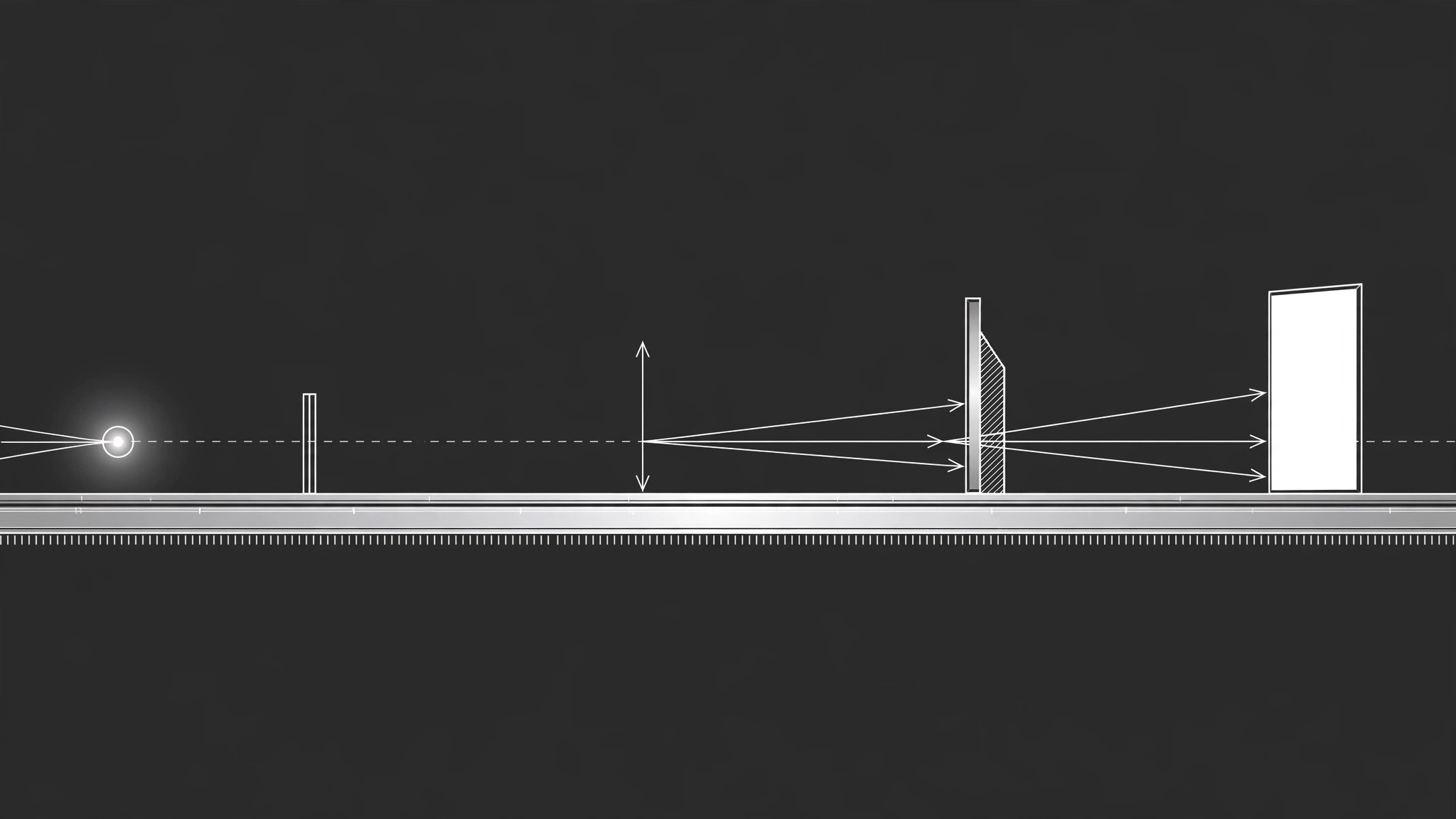
One SKILL.md (the playbook) + one starter template. A preview:
Optical Bench Diagram
When to use
- You need a diagram of a lens, mirror, or prism experiment for a lab handout, a lesson, or a report
- A student asks "what does the setup actually look like?" and a paragraph of description isn't landing
- You're documenting an experiment so someone else can rebuild it from the diagram alone
- You want a clean top-view bench layout showing where each component sits on the rail
- You're explaining ray behavior — focal points, reflections, refraction — and need rays drawn, not just described
Workflow
- List the components (input: experiment description → output: component list)
Name every physical piece in the setup: light source, slits, lenses (converging or diverging, with focal length), mirrors (flat, concave, convex), prisms, screens, detectors, and the bench or rail itself. Include the numbers you know — focal lengths, distances between components, wavelengths — and mark the ones you're estimating. A diagram built from a guessed focal length silently teaches the wrong geometry, so guesses get flagged, not hidden. - Fix the beam path (input: component list → output: beam-path sequence)
Trace the light in order, from source to detector: source → slit → lens → mirror → screen. Write it as a numbered sequence before drawing anything — this is the spine of the diagram. For each interaction, note what the light does: passes straight through, converges, diverges, reflects at a stated angle, or splits. If the path branches (a beam splitter, a prism spreading wavelengths), list each branch separately so none gets dropped. - Lay out the bench (input: beam-path sequence → output: top-view layout)
Draw the top view first: a horizontal rail as the baseline, components placed along it at their stated distances, rays drawn as straight lines with arrowheads showing direction. Keep one consistent direction of travel — left to right — unless the setup genuinely folds back on itself. Use standard symbols: a lens as a vertical line with arrowheads at the ends (outward for converging, inward for diverging), a mirror as a thick line with hatching on the back, a source as a small lamp or aperture symbol. - Label everything (input: layout → output: labeled diagram)
Every component gets a label with its name and its key value ("Converging lens, f = 10 cm"). Every ray gets a label where it changes ("reflected ray", "refracted ray"). Mark the optical axis as a dashed line, mark focal points with F and 2F where they matter, and add a scale bar or a distance annotation between components. A diagram with unlabeled rays forces the reader to guess which line is which — the labels are the diagram.
Template preview
Optical Bench Diagram — Setup Template
One diagram, one setup. List the components before drawing anything.
Experiment
Title: {experiment name} Purpose: {what this setup demonstrates or measures} Top view / side view: {top view is the default; note side view if needed}
Component list
Estimated values (flagged, not hidden): {value + why it's an estimate}
Beam path (numbered, source → detector)
- {source} → {next component}: {what the light does}
- {component} → {next component}: {what the light does}
- {branch, if any}: {component} → {detector}: {what the light does}
Diagram checklist
[ ] Rail baseline drawn, left-to-right beam travel